In Detail: How Did the Spudder on an Old Drilling Rig Work?
Columnist John Schmitt Explains Spudding System on a Bucyrus-Erie 20W
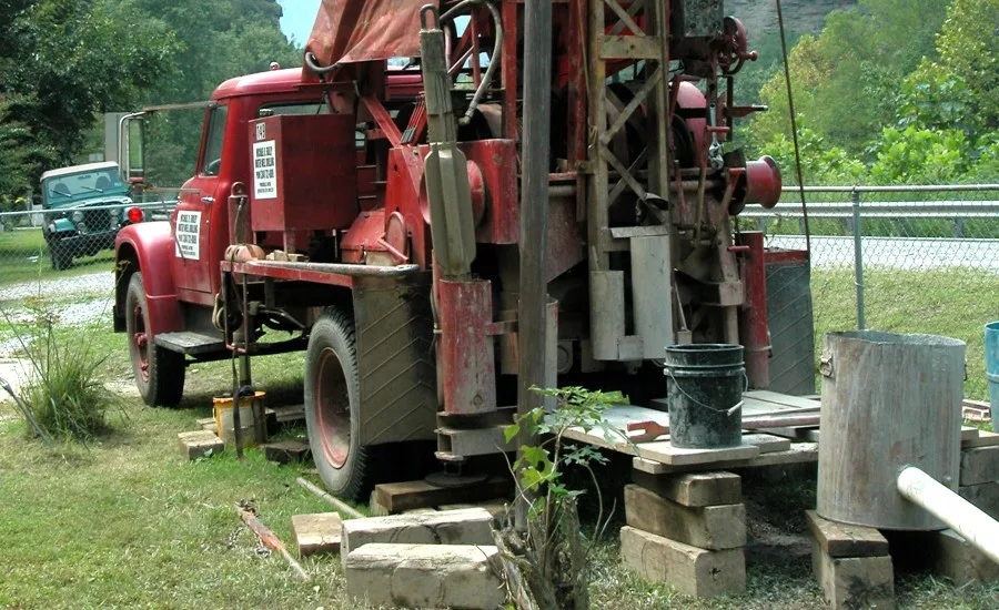
A lot of spudder rigs shared the same design as the Bucyrus-Erie 20W.
Source: Pollinator / CC BY-SA 3.0 / Wikimedia Commons
Readers, I have been going over details of a Bucyrus-Erie 20W spudder rig. You don’t see many of these rigs around anymore, at least not on the job here in southern Michigan. You also don’t talk to many drillers, active or retired, who have experience running a spudder. I know of a successful contractor who operates in my county, and they run several rotaries and have one spudder they rarely use. A grand total of two people, one semi-retired, know how to operate it. So perhaps this series of columns has some historical significance.
As promised last time, this column discusses the spudder system of the 20W. This was, of course, the most important part of a spudder rig. If this mechanism failed, the rig did not make hole, which is precisely what it was supposed to do. As with almost all modern spudders the 20Ws were gear driven. A small pinion on the jackshaft controlled by a friction clutch drove a much larger spudder gear. Virtually all spudders shared this design, although there was a company who had a successful line of spudders driven by V-belts that mainly served the oil industry. Needless to say, those rigs ran very quietly. I saw one in action on a couple of occasions and consider it a good design.
The crank pin directly attached to the spudder gear of the 20W. This gave the drill line its up and down motion. Operators could adjust this crank pin, inserting it into one of three holes in the spudding gear. I believe the strokes afforded by these different holes were 18, 24 and 30 inches. Most everyone running the rig as a cable tool ran on the longest stroke. I did this much of the time, but sometimes ran the 24-inch for a few more strokes per minute. I do know people who ran a 20W as a jetting machine, and they ran usually in the short stroke. I believe this 18-inch stroke was meant for fishing.
The crank pin was just a big, round shaft of steel about 2 inches long. It had a flange on the outside and attached to the spudder gear with a large nut. The rig came with a big hex wrench to tighten or loosen this crank pin, and I used to tighten the crank pin by hitting the hex wrench with a hammer. The pitman connecting the spudder gear to the spudder beam had bronze bushings on both ends. While generous in size and equipped with grease fittings at both ends, these bushings tended to wear quickly. When I bought this rig, I found among the parts I received a 5 gallon pail full of crank pins. Even if greased every four hours, the crank side of the pitman seamed to wear faster than I’d expect. Was this a design flaw? I don’t know.
At its upper end, the pitman could connect to the spudding beam in two locations. Each connection was simply a large bolt that held a bushing, and held in place with not one but two large hex nuts. In the drilling position, the pitman connected closest to the pivot point of the spudding beam. This gave a somewhat slow pickup of the drill line, but a faster drop. Of course, a faster drop to the tools was a desirable thing. For bumping back pipe, done by several methods I will not go into here, the pitman used the connection further away from the spudding beam’s pivot point. Due to its relations with the crankshaft, this gave a quick up stroke with a slower down stroke. This was a good idea that did not add much efficiency to the 20W’s ability to bump back pipe.
The main competition to the 20W was another popular rig that differed in many ways from the B-E. It had a chain-driven bull reel, a separate clutch for the casing reel and, most importantly, a centrally mounted spudding gear with two crank arms, one on each side. This was supposed to be a balanced design and easier on the mechanism.
There were two big differences between this design and the B-E. The competition used anti-friction bearings in the wrist pins of the two pitmans. I believe these were roller bearings. I would have to say this was probably a big advantage over the bushing of the crank pin of the 20W. Both these rigs would make hole and last a long time, so perhaps the difference between the single and double pitmans was just a talking point — like Ford versus Chevy or John Deere versus International.
The other major difference between these rigs was the direction the crankshaft turned. On a Bucyrus-Erie the crank pin was between the crankshaft and the jackshaft on the up stroke of the tools. On the competition, the crank pins were outside of the crankshaft on the up stroke. Bucyrus-Erie’s catalogs made a big point of this between-the-shafts position. People argued about which was better, but I don’t think there were any differences if both machines were properly maintained and greased. On the shop-built rig I ran for many, many years, its two crank pins were like B-E’s competition and never gave us trouble. I think this was just another talking point and rotation of the crankshaft really made no difference.
I am writing this in early November and we have had a very nice fall here in southern Michigan. My infamous lawn is still quite green, although it has gone dormant — growing very little, if at all. Over the weekend we had a few snow squalls, a harbinger of things to come and a reason for you readers in the South to smile. Yesterday, I ran a service call at a lake cottage and worked both inside and outside. Working outside, I was on the lake side of the cottage. With a high wind blowing, it felt downright cold even with a heavy jacket — again, the harbinger of things to come. When you read this, it may be past Thanksgiving. I hope you and yours had a good celebration despite the continuing Covid-19 situation. Next time, I will do more detail on the 20W (which maybe you’re getting a little tired of, but I hope not).
For more John Schmitt columns, visit www.thedriller.com/schmitt.
Looking for a reprint of this article?
From high-res PDFs to custom plaques, order your copy today!


